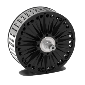
Multi Phase Axial Flux Motors
Low Cogging Torque, Longer Service Life and more Power
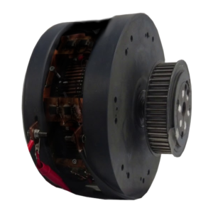
Brushed Axial Flux Motors
Low Voltage Motors with Brush Commutation and Simple Drive Control architecture.
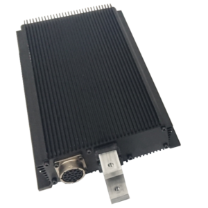
Pure Torque Controlled Drives
Maximizing System efficiency in Motoring and Regen Modes
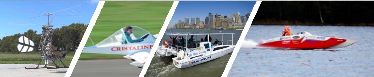
Customize your Package
Ready-To-Race-Technology with Custom Motor Design Support
Previous
Next